


Digital Integrated Circuits
We are leading Supplier & Distributor for the Digital Integrated Circuits which also includes Digital Integrated Circuits & Diode Module since 2011
Digital Integrated Circuits
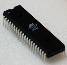
.jpg) We are engaged in offering a steadfast range of Integrated Circuits (Micro Prossesor) to our esteemed clients. These integrated circuits are highly used in electronic industries for application in cellular phones, computers, and digital microwave ovens. Our range of integrated circuits is procured from the renowned vendors of the market.
We are engaged in offering a steadfast range of Integrated Circuits (Micro Prossesor) to our esteemed clients. These integrated circuits are highly used in electronic industries for application in cellular phones, computers, and digital microwave ovens. Our range of integrated circuits is procured from the renowned vendors of the market.
Digital Integrated Circuits
.jpg) Very high speed integrated circuit (VHSIC)
Very high speed integrated circuit (VHSIC)
Hardware
Description
Language
VHDL is a high level language through which it is possible to define the functionality of an electronic system both in a structural way and purely behavioural.
Its employment in the design of digital integrated circuits (both Custom and FPGA) is considered fundamental.
Diode Module
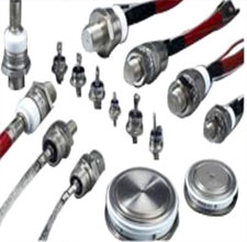
 Complete range of power modules including pressure type and soldering type are very available to us. For example, Thyristor module MT25A~800A, 500~2500V; Fast turn-off thyristor modules 150A~400A, 600~1600V; Thyristor/Diode modules MF25A~800A, 500~2500V; Non-isolated type modules 100~300A, 500~2500V; Single/Three phase rectification bridge modules 50A~150A, 600~2000V etc
Microcontroller
 Microcontrollers are hidden inside a surprising number of products these days. If your microwave oven has an LED or LCD screen and a keypad, it contains a microcontroller. All modern automobiles contain at least one microcontroller, and can have as many as six or seven: The engine is controlled by a microcontroller, as are the anti-lock brakes, the cruise controland so on. Any device that has a remote control almost certainly contains a microcontroller: TVs, VCRs and high-end stereo systems all fall into this category. Nice SLR and digital cameras, cell phones, camcorders, answering machines, laser printers, telephones (the ones with caller ID, 20-number memory, etc.), pagers, and feature-laden refrigerators, dishwashers, washersand dryers (the ones with displays and keypads)... You get the idea. Basically, any product or device that interacts with its user has a microcontroller buried inside.
Power Transistor
![]() I have already sent you the write-up for the early "Transistor Products" (Power Trannies) linee-up which covers the era from 1953-1955. This current period covers the next generation of power transistors from late 1955 to 1957. It was at this time that the Clevite Corporation decided to call the product line by the full "Clevite Transistor Product" name. Even though they had bought Transistor Products back in 1953 the only indication of the new ownership was the use in 1954 of the "C/TP" logo that appeared on their later "X-" series of products. So ads in 1956 started using the new "Clevite Transistor Products" name and their products from then on were just marked "Clevite" or "CTP".
I have already sent you the write-up for the early "Transistor Products" (Power Trannies) linee-up which covers the era from 1953-1955. This current period covers the next generation of power transistors from late 1955 to 1957. It was at this time that the Clevite Corporation decided to call the product line by the full "Clevite Transistor Product" name. Even though they had bought Transistor Products back in 1953 the only indication of the new ownership was the use in 1954 of the "C/TP" logo that appeared on their later "X-" series of products. So ads in 1956 started using the new "Clevite Transistor Products" name and their products from then on were just marked "Clevite" or "CTP".
Top row , L-TO-R: We know from Marrows 1956 book, "Transistor Engineering", that Clevite TP first developed the wide flange top-hat power transistor in early 1956. The far left item is probably an early pre-production device from late 1955 as it's base is made of copper. All the later ones were made of steel. The far right two items are a Clevite CTP-1002, dated from 26th week, 1956. This is the first high power transistor from the new product design, rated at 25 watts dissipation, on 28 volts, as was the new CTP-1003. Additionally, they released a 12 volt line called the CTP-1004, CTP-1005 and CTP-1006, all rated at 25 watts dissipation. These were all PNP Germanium types. All of these had the exhaust tip on the top-hat cover and unlike CBS, did not cover the tip with anything.
bottol Row, L-TO-R: By mid 1956 Clevite TP had come out with their own TO-3 line of transistors. First was the 2N257, middle item, and this was followed by the 2N268 and 2N268A - all rated at 25 watts dissipation. By late 1956 the 2N297 (far right) and the 2N297A were released, rated at 35 watts. As can be seen in the early 1956 devices, far left two and the far right, Clevite was still using a top exhaust construction method as the round exhaust dimple shows on the top cover, although without any tip. The far left two items are likely early production samples as they do not have any recognizable numbers but are both from 1956
Rectifier Diodes
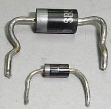
 Our products are widely used in computers, communication, household appliance, automobile electronics, industrial automation instrument testing equipment, lighting electrical appliance, electronic tools and other related field.
Our main products including diodes, transistor, super fast recovery rectifiers, high efficiency rectifier, fast recovery rectifier, schottky barrier rectifiers, bridge rectifier, TVS diode and so on.
It will be a great pleasure to receive your inquiries of any of the items against which we will send you our lowest quotation.
SMD Transistor
![]() We stock and sell chip transistors of the following makes:
We stock and sell chip transistors of the following makes:
Makes: Philips, NXP, Motorola, Fairchild, NEC, Zetex, ROHM, Infineon
Types: Chip Transistors, Darlington Transistors, Resistor equipped Transistor, Wideband Transistor, Digital & Power Transistors
Package: SOT23,SOT89, SOT223, SOT232, SOT323
Schottky Diode
 The schottky diode or schottky barrier rectifier is designed for uses in high efficiency rectification essential for applications like switched mode power supply (SMPS) circuit, switching regulator and etc. If you observe any electronic schematic diagrams and layout, schottky rectifier symbol looks exactly the same as a normal diode.
Even the outlook, shape and designed just like a normal diode. The major difference between a normal diode and schottky barrier diode is the part number. Because of the same outlook, many electronic repairers thinks that measuring schottky diodes is just the way as testing a normal diode. If you use the normal diode checking method to test on schottky diode then chances are high that you will not solve the problem.
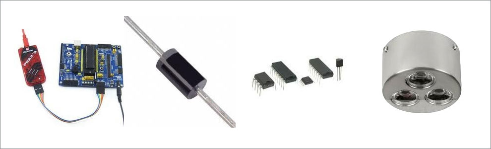
Stepper Motor Driver IC
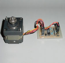 Recently, a popular stepper motor drive solution has relied on an outdated stepper motor driver IC which can be difficult to source. An alternative design idea is offered in this technical article by using a complex programmable logic device (CPLD) to perform with currently available components.
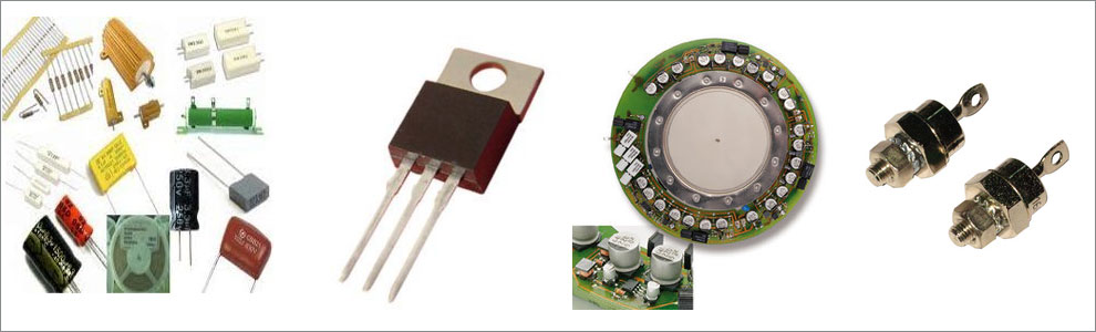
Thyristors
 Before the discovery of thyristors, thyratrons were used for industrial control, but now they have been replaced by the thyristors because of the following drawbacks of thyratrons.
1. Thyratron needs a large anode-to-cathode voltage and a separate filament supply whereas the thyristor needs only one main supply and a control signal.
2. Thyratron takes long time in ionising and deionising and, therefore, is unsuitable for higher frequencies (beyond 1 kHz). A thyristor can operate over a wide range of frequencies because it can withstand as high as 200 A/micro seconds rate of rise of current.
3. A thyristor has much smaller turn-on and turn-off times in comparison to those of a thyratron.
4. Because of the filament and hitting of anode by accelerated electrons, the life of thyratron is much smaller than that of a thyristor.
5. Thyratron is less reliable than thyristor.
6. Thyratron have internal losses much larger than those of a thyristor.
7. Thyratron is bulkier than thyristor because in thyratron large spacing is required to be provided to avoid any arc-backs and unwanted flash-overs.
A thyristor is a current controlled device, while the thyratron is a voltage controlled device. This results in different design of control circuits for them.
Transducers
![]()
General Technical Specifications for all single BLT transducers
- Design: Sandwich piezoceramic transducer.
- Piezoceramic diameters: 35, 38, and 50 mm (for different powers).
- Power ranges: From 50 W up to 200 W continuous RMS ultrasonic power (out of this range acceptable on request).
- Operating frequencies: From 20 kHz to 60 kHz (other freqencies available on request ).
- Multiple frequency operation: All transducer models can also be driven on several resonant frequencies (on natural, lowest resonance, or on several higher harmonics and oscillating modes).
- Resonance type: Operating in series or parallel resonance possible (depending on ultrasonic generator and matching).
- Mechanical quality factor: Between 700 and 1000, both in the series and parallel resonance (higher upon request).
- Front emitting mass: The highest available aircraft grade aluminum.
- Back mass: Stainless steel.
- Central bolt: The highest available aircraft grade.
- Electrodes (modifiable on request): Special nickel alloy - non-corrosive, high thermal and electro conductive alloy (having very low surface friction).
- Sealing: External surfaces of piezoceramics are protected against moisture and humidity by silicone coating.
- Recommended use (BLTC): Ready for adhesive bonding/bolting fixation to a cleaning tank (modifiable upon request).
- Applications (BLTC): Easy applicable for ultrasonic cleaning, liquid processing, and similar applications.
Special Options (BLTC)
- Any custom design is acceptable, based on different resonant frequency, different geometry, given drawings, given model, different metals, or given description.
- An optimized copy of any existing transducer can be produced, offering identical or superior performance to the manufacturer's original, and produced in the shortest possible time (between 1 and 3 weeks ready for delivery and mass production).
- Small orders acceptable.
Example of a custom made cleaning transducer (BLTC) Characteristics:
- fs = 25 kHz (=) series resonant frequency
- Cinp (at 1 kHz) = 3.7 nF
- Amplitude (peak-to-peak, sinusoidal): up to 10µm (depending on resonant mode, acoustic coupling and loading conditions)
- 100 W continuous RMS power when bonded/bolted to the cleaning vessel (fs = constant)
- 50 to 75 W continuous RMS in a large frequency sweeping (fs = fso ±10% of fso)
- 200 W, maximal (peak) power with sinusoidal (low frequency) amplitude modulation (fs=constant)
Transistors
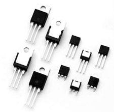
![]() Transistors are active components and are found everywhere in electronic circuits. They are used as amplifiers and switching devices. As amplifiers, they are used in high and low frequency stages, oscillators, modulators, detectors and in any circuit needing to perform a function. In digital circuits they are used as switches.
Transistors are active components and are found everywhere in electronic circuits. They are used as amplifiers and switching devices. As amplifiers, they are used in high and low frequency stages, oscillators, modulators, detectors and in any circuit needing to perform a function. In digital circuits they are used as switches.
There is a large number of manufacturers around the world who produce semiconductors (transistors are members of this family of components), so there are literally thousands of different types. There are low, medium and high power transistors, for working with high and low frequencies, for working with very high current and/or high voltages. Several different transistors are shown on 4.1.
The most common type of transistor is called bipolar and these are divided into NPN and PNP types.
Their construction-material is most commonly silicon (their marking has the letter B) or germanium (their marking has the letter A). Original transistor were made from germanium, but they were very temperature-sensitive. Silicon transistors are much more temperature-tolerant and much cheaper to manufacture.
Voltage Transistor
![]()
BU508A, BU508D, BU208A, BU208D, BUT11AF, BUT11AX, BUT12A, BUT12AF, KA7805, KA7812 and so on.
Features:
- BU508A
- NPN, PCM 125W, IC 8A, VCBO 1500V, VCEO 700V, VEBO 7V, HFE MIN 8, MAX 30
- BU508D
- NPN, PCM 125W, IC 8A, VCBO 1500V, VCEO 1500V, VEBO 7V, HFE MIN 8, MAX 30
- BU208A
- NPN, PCM 125W, IC 5A, VCBO 1500, VCEO 700, VEBO 7V, HFE MIN 2.5, MAX 30
- BU208D
- NPN, PCM 125W, IC 5A, VCBO 1500V, VCEO 1500V, VEBO 7V, HFE MIN 2.5, MAX 30
- 2SC1959
- NPN, PCM 50W, IC 10A, VCBO 1400V, VCEO 700V, VEBO 6V, HFE MIN 8, MAX 40, PACKAGE TO-3PN
Zener Diode
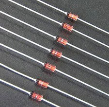 The function of a Zener diode is quite unique and this is a kind of diode that differs from most other regular diodes. Before you understand the complete function of a Zener diode, you need to take a look at the major functioning of a regular diode. In case of an ideal diode, the function is divided into two parts, forward and reverse bias. There is nothing much to talk about in forward bias as it is the reverse bias which is responsible for major discrepancies between ideal and Zener diode.
Diodes
.jpg)