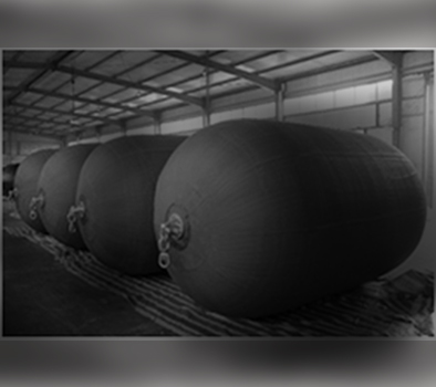
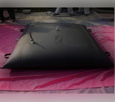
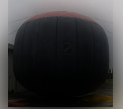
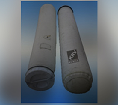
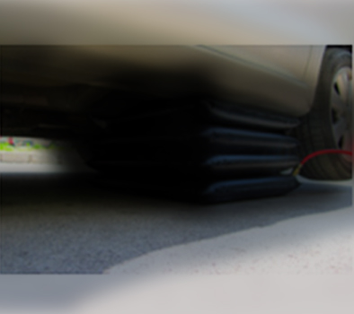
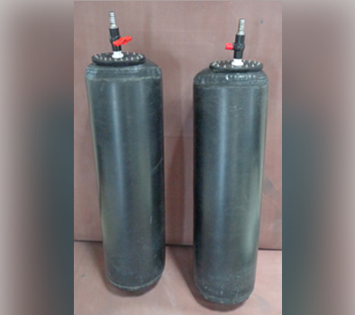
Rubber Bladders
OVERVIEW
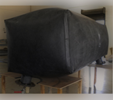
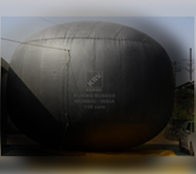
Kurwa Rubber design, draw, manufacture & supply KIPFLEX cylindrical (vertical & horizontal orientation) rubber bladders in compressible and expandable variants, in various grades of rubber to suit clients’ specific service conditions based on their media, temperatures and pressures.
Kipflex bladders are available in a volume/capacity ranging from 200 ltrs to 150,000 ltrs made from buna-n (fg), butyl, epdm, neoprene & hypalon grades of rubber with cold bonding process. these bladders have nylon-66, polyester, aramid, heavy duty reinforcements generating high burst pressures upto 75 kg/cm2 in mullen burst astm d-751 test procedure.
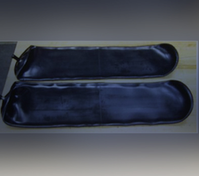
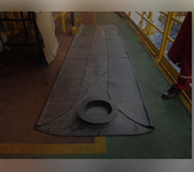
The main feature of our compressible bladders is that they are highly resilient, portable, flexible collapsible, light weight, easy to handle & install, abrasion resistant & durable.
All Kipflex bladders are accompanied by material, dimensional & test certificate, installation procedures, warranty certificate, qap with drawings, site repair kit (with manual) & traceability code. Kurwa Rubber also offer techinical assistance during installation process, by our qualified engineering team.
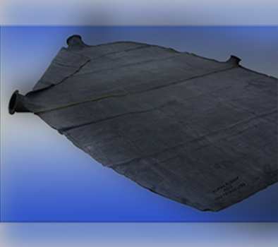
Kipflex bladder have a wide range of elastomeric connecting flanges complying to various standards like asa#150-300, pn10-16, bs-10 etc or even flat clamping type as required by the clients.
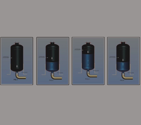
AIR IN BLADDER (VERTICAL)
The air/nitrogen charge is contained within the bladder inside the tank. The charge does not come into contact with the liquid in the tank and so cannot be absorbed. Air charge losses due to absorption are therefore minimal.
The pumped media from the mainline, flows in and out of the vessel and it will come in contact with the bladder, so compatible materials must be selected.
The bladder is often made from a High Tensile Rubbers with or without reinforcements, in Neoprene, Nitrile(Buna-N), Food Grade Butyl or Hypalon Rubbers, and may be expanded to fit the entire vessel. The Bladders are fitted with a Flange at the top as per Client’s vessel details.
The bladder will typically be pre-charged with Air/Nitrogen after installation (Fig.1) with a pre-determined pressure as per surge/hydraulic analysis, to give the correct operating level in the tank when the unit is connected to the mainline at the working pressure.
When the mainline valve is opened, the water/media will enter the vessel under static condition and begins to compress the Gas filled bladder (Fig.2). The static line pressure will be higher than the pre-charge pressure. The water/media entering the vessel will further compress the pre-charged Bladder until a perfect balance is created between the water and the compressed bladder.
On Pump Tripping or shutting the surge created in the mainline will push the water into the vessel. This pressure will be absorbed by the compressing bladder and effectively reflex pressure will be applied on the surge. After multiple hammerings & oscillations, it will even out the pressure (Fig3,4) of the mainline and create a static state, without damaging the pipeline. Eventually the entire system will return back to dynamic state( Fig.2) for the next surge.
Capacities available are from 100 liters to 100,000 liters.
Video
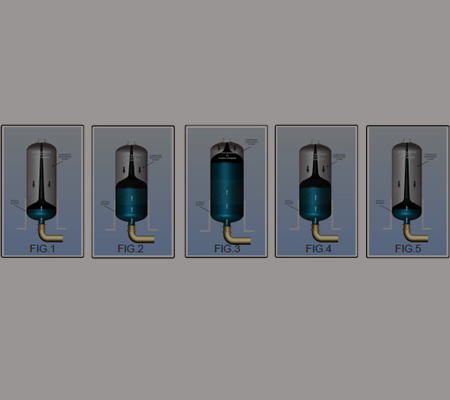
WATER IN BLADDER (VERTICAL)
Video
The air/nitrogen charge is contained within the tank, whilst the liquid from the mainline flows in and out of the bladder. Like the air in bladder design, the liquid does not come into contact with the tank nor the air charge, so again, the air charge cannot be absorbed by the pumped media and so air losses due to absorption are minimal.
The bladders are made from a High Tensile Rubbers with or without reinforcements, in Neoprene, Nitrile(Buna-N), Food Grade Butyl or Hypalon Rubbers, and may be expanded to fit the entire vessel. The Bladders are fitted with a Flange at the Bottom as per Client’s vessel details.
For this design the whole tank is pre-charged at installation with a pre-determined pressure to give the correct operating level in the tank (FIG.1) when the unit is connected to the mainline and at the desired operating pressure. A grid Plate or diffuser can be placed at the outlet of the vessel to prevent the bladder from being sucked into the mainline at low pressures. They are provided with Lugs/Hooks at the Top for hanging support.
When the mainline valve is opened, the water/media will enter the Bladder under static condition and begins to compress the Gas filled Tank (Fig.2). The static line pressure will be higher than the pre-charge pressure of the Tank. The water/media entering the Bladder will further compress the pre-charged Tank until a perfect balance is created between the Water in Bladder and the compressed air in Tank.
On Pump Tripping or shutting the surge created in the mainline will push the water into the Bladder. This pressure will be absorbed by the compressed air in the Tank and effectively reflex pressure will be applied on the surge. After multiple hammerings & oscillations, it will even out the pressure(Fig3,4) of the mainline and create a static state, without damaging the pipeline. Eventually the entire system will return back to dynamic state( Fig.5) for the next surge.
Capacities available are from 100 liters to 100,000 liters.
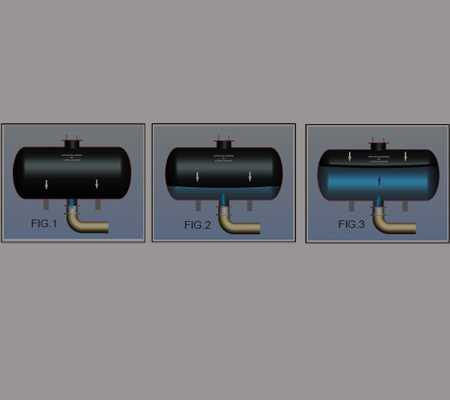
AIR IN BLADDER (HORIZONTAL)
The air/nitrogen charge is contained within the bladder inside the tank. The charge does not come into contact with the liquid in the tank and so cannot be absorbed. Air charge losses due to absorption are therefore minimal.
The pumped media from the mainline, flows in and out of the vessel and it will come in contact with the bladder, so compatible materials must be selected.
The bladder is often made from a High Tensile Rubbers with or without reinforcements, in Neoprene, Nitrile(Buna-N), Food Grade Butyl or Hypalon Rubbers, and may be expanded to fit the entire vessel. The Bladders are fitted with a Flange at the top as per Client’s vessel details.
The bladder will typically be pre-charged with Air/Nitrogen after installation (Fig.1) with a pre-determined pressure as per surge/hydraulic analysis, to give the correct operating level in the tank when the unit is connected to the mainline at the working pressure.
When the mainline valve is opened, the water/media will enter the vessel under static condition and begins to compress the Gas filled bladder (Fig.2). The static line pressure will be higher than the pre-charge pressure. The water/media entering the vessel will further compress the pre-charged Bladder until a perfect balance is created between the water and the compressed bladder.
On Pump Tripping or shutting the surge created in the mainline will push the water into the vessel. This pressure will be absorbed by the compressing bladder and effectively reflex pressure will be applied on the surge. After multiple hammerings & oscillations, it will even out the pressure (Fig3) of the mainline and create a static state, without damaging the pipeline. Eventually the entire system will return back to dynamic state( Fig.2) for the next surge.
Capacities available are from 100 liters to 100,000 liters.
Video
WATER IN BLADDER (HORIZONTAL)

Video
The air/nitrogen charge is contained within the tank, whilst the liquid from the mainline flows in and out of the bladder. Like the air in bladder design, the liquid does not come into contact with the tank nor the air charge, so again, the air charge cannot be absorbed by the pumped media and so air losses due to absorption are minimal.
The bladders are made from a High Tensile Rubbers with or without reinforcements, in Neoprene, Nitrile(Buna-N), Food Grade Butyl or Hypalon Rubbers, and may be expanded to fit the entire vessel. The Bladders are fitted with a Flange at the Bottom as per Client’s vessel details.
For this design the whole tank is pre-charged at installation with a pre-determined pressure to give the correct operating level in the tank (FIG.1) when the unit is connected to the mainline and at the desired operating pressure. A grid Plate or diffuser can be placed at the outlet of the vessel to prevent the bladder from being sucked into the mainline at low pressures. They are provided with Lugs/Hooks at the Top for hanging support.
When the mainline valve is opened, the water/media will enter the Bladder under static condition and begins to compress the Gas filled Tank (Fig.2). The static line pressure will be higher than the pre-charge pressure of the Tank. The water/media entering the Bladder will further compress the pre-charged Tank until a perfect balance is created between the Water in Bladder and the compressed air in Tank.
On Pump Tripping or shutting the surge created in the mainline will push the water into the Bladder. This pressure will be absorbed by the compressed air in the Tank and effectively reflex pressure will be applied on the surge. After multiple hammerings & oscillations, it will even out the pressure(Fig3) of the mainline and create a static state, without damaging the pipeline. Eventually the entire system will return back to dynamic state( Fig.1) for the next surge.
Capacities available are from 100 liters to 100,000 liters.
APPLICATIONS OF RUBBER BLADDERS & INFLATABLES
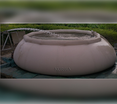
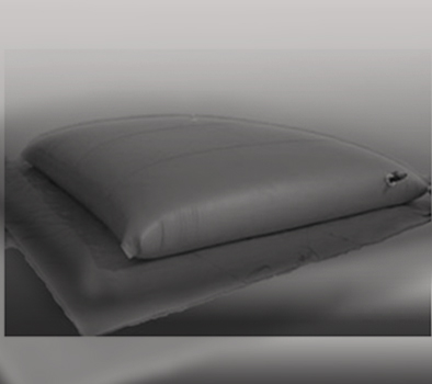
We offer Highly resilient, portable, flexible, collapsible, Light weight, Durable, Economical, easily installable Rubber Bladders, Tanks and inflatables for various applications and uses. The Bladders / Tanks / inflatables can handle Potable water, Petroleum Products, Chemicals, Industrial Oils & Gases. These Bladders can be made in any shape/ dimensions required by you in capacities ranging from 200 ltrs to 200,000 ltrs with various suitable connections and accessories for following applications -
- Bladders/Membranes for Hydro-Pneumatic Tanks, Accumulators, Hammer Tanks
- Pillow Tanks for Gas & Water
- Emergency Spare Fuel Pillow Tanks
- Portable Tanks for Petroleum Products
- Air Cushion & Splitting Bags for Marble & Granite
- Defueling Tanks
- Rain Harvesting Tanks
- Gas Collection and sampling Bladders
- Portable Tanks for Irrigation & Aquaculture
- Inflatable Dock Fenders & Dry Docking Floats
- Ship Launching Inflatable Marine Air Bags
- Air Bags for Accident Relief Operations
- Air Bags for Material Handling Equipments
- Air Bags for Lifting Heavy Equipments
- Potable Water Backpacks for Trekking
- Air Operated Inflatable Seals
- Inflatable Water Ponds & Reservoirs
- Packaging Air Bags for Containers
- Inflatable Rubber Air Bags for Rafts
- Dunnage Air Bags
- Inflatable Dams & Airbag base Bridges
- Air/Gas Balloons
- Air Bag Stoppers
- Impact Bladders