Oil Water Seperation Unit
 In the modern TPI System, the separating surface area is increased vertically by the addition of a number of parallel plates mounted at an inclination. This not only affords a dramatic space saving but also facilitates very small separating diameter.
The K-pack TPI consists of a plate pack constructed of closely spaced corrugated plates inclined at a 45° angle or more, depending on the application. Waste water flows through these plated either parallel to the corrugations in "Counter-current Flow" or at right angles to the corrugations in "Cross Flow". Under laminar flow conditions, the short distance between the inclined plates is now the only distance over which the pollutants have to rise or sink before they are intercepted and separated from the mother fluid.
The Theoretical Basis
Imagine a rectangular tank with a surface A containing a liquid to a height H (see figure 1). Flow through the tank is homogeneous and the flow rate = Q The settling or rising velocity of a particle with diameter d is governed by Stoke's Law:
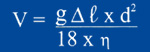
It follows that the tank surface A is inversely proportional to the square of diameter d of the smallest particle which will completely separate. An increase in the efficiency of a separator can, as a result, only be achieved by a considerable increase in the surface A, which leads to the installation of large tanks with large surface area A. The effectiveness of such large tanks is limited due to factors like:
- Turbulence and short-circuit currents.
- Variation in ambient temperature.
- Temperature gradients in the liquid.
- Surface wind load.
The TPI Seperation Principle
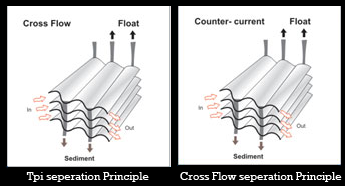 In the modern TPI System, the separating surface area is increased vertically by the addition of a number of parallel plates mounted at an inclination. This not only affords a dramatic space saving but also facilitates very small separating diameter. The K-pack TPI consists of a plate pack constructed of closely spaced corrugated plates inclined at a 45° angle or more, depending on the application. Waste water flows through these plated either parallel to the corrugations in "Counter-current Flow" or at right angles to the corrugations in "Cross Flow". Under laminar flow conditions, the short distance between the inclined plates is now the only distance over which the pollutants have to rise or sink before they are intercepted and separated from the mother fluid.
Application:
• Mineral oil refineries, oil extraction, offshore platforms
• Tank storage farms
• Ballast water treatment
• Petrochemicals
• Galvanizing metal; mining industry
• Edible oil refining
• Foodstuffs industry
• Paper & pulp industry
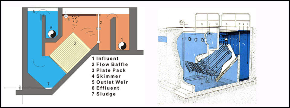
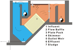
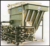
Cross Flow Seperator (PCI)
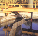
The Cross flow separator system permits simultaneous separation of floating and settling materials like oils, fibres, sand etc.. But are also individually applicable as oil and solids separators. The raw water containing oil and/or suspended solids passes in horizontal direction between the closely spaced plates in the plate pack. Completely laminar flow conditions are established while the water flows across the plate pack from the inlet to the outlet side. Laminar and stable flow conditions are essential conditions for the effective gravity separation of the water, oil and/or the suspended contaminants.
Oil separation
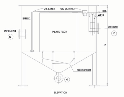
In the course of passing through the plate pack from inlet to outlet, the oil floats upwards info the tops of the corrugations and rises up the incline of the plate to the surface of the separator, where it is removed by a skimmer.
Solids Separation
The solids move towards the Bottoms of the corrugations and slide down the incline of ' the plate. From there the separated solids are collected in the sludge compartment of the separator to be partially dewatered and transported by a shaft less spiral conveyor and intermittently discharged through a blow-off valve (optional). Settled sludge cannot decontaminate the treated water. Oil and solids move in separate directions, but both perpendiculars to the flow of water, eliminating particle re-entrainment completely.
All K-Pack separators are custom built with respect to the number of plates in the pack, the length of the plates, the distance between the plates and the plate incline. The number and the length of plates is determined as a function of the raw water flow rate to be processed in the separator. The distance between the plates is depending upon the concentration of solids / sludge in the raw water. The incline of the plates is set between 45 and 60 degrees depending upon the general nature of the Oil and/or sludge, (density, viscosity, concentration).
The systems are fabricated in mild steel and other materials are available on request. The oil separators are standard with oil and skimpipe and 45 degree shaped compartment. The solids separators are optionally with a shaftless conveyor in the sludge compartment.
In the corrugation tops a very high oil concentration is established. This is the ideal condition for oil coalescing to take place (formation of large oil droplets out of many small oil droplets). In the corrugation bottoms a high sludge concentration is established. This is the ideal condition for particle agglomeration to take place (formation of heavy particles from small and relatively light particles)
Applications
• Mineral oil industry
• Edible oil industry
• Metal industry
• Ceramic industry
• Galvanic industry
• Mines
• Sand separation after washing of contaminated soil
• Food industry
GA Drawings
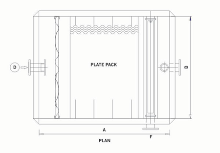
Standard Units
| PCI | 10 |
20 |
30 |
40 |
100 |
200 |
300 |
| Capacity m3 | 10 |
20 |
30 |
40 |
100 |
200 |
300 |
Effective Plate surface, m2 |
14 |
29 |
43 |
57 |
143 |
286 |
429 |
Over Flow Rate m/hr |
0.7 |
0.7 |
0.7 |
0.7 |
0.7 |
0.7 |
0.7 |
| Length A mm | 1400 |
2000 |
2000 |
2600 |
2200 |
4200 |
6200 |
| Width-B mm | 2000 |
2000 |
2600 |
2600 |
3200 |
3200 |
3200 |
| Height Cmm | 2500 |
2500 |
3000 |
3000 |
3100 |
3100 |
3100 |
| Inlet D mm | 80 |
100 |
100 |
150 |
200 |
350 |
450 |
| Outlet Emm | 100 |
150 |
150 |
150 |
200 |
250 |
300 |
Oil Skimmer F mm |
80 |
80 |
80 |
100 |
100 |
100 |
100 |
| Sludge G mm | 80 |
100 |
100 |
100 |
150 |
150 |
150 |
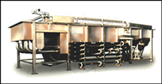
Dissolved Air Flotation Units
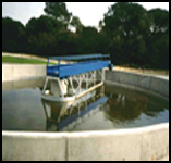
 DAF is a gravity seperation process whereby the separation of two phases is achieved by increasing the specific gravity difference of the two phases. This is achieved by attaching micro air bubbles, brought about by saturating water with air under pressure, and then expanding the wa terstream through valves to atmospheric pressure. These micro bubbles nucleate onto the solid particles to be separated, thus lowering the specific gravity and allowing contaminants to rise to the surface.
Suspended solids, grease and oil are very efficiently removed by DAF, and a combination of screening and DAF results in BOD/COD removals upto 60% depending on the application.However, a combination of flocculation and floatation can result in BOD removals of around 80-90%.
PWL
 For wastewater containing high solid content, it is necessary to create a sufficient retention time for prewatering of the skimming.
The PWL series Flotation unit have been designed for capacities up to 200m3/hr. (As standard) Higher capacities are realized by combining or expanding systems. Standard construction is in carbon steel, but other material is possible. DAF systems in concrete are also possible. Saturation of air in water can be carried out by dosing the air in suction side of the Aeration pump. Dissolution takes place by Henry law , and the turbulence and energy in the pump provide excellent condition for the process.
Alternately, use can be made of saturation vessel, of conventional design for the air to Dissolve in the water. The recycle flow is mixed with the wastewater in the flotation unit, through a pressure pipe. Air bubbles formed adhere to the particles and give them buoyancy to float rapidly through surface These system donot use plate packs and are open tank, low unit separator, with the aeration point in the inlet as well as the sides of the tank to ensure excellent aeration along the entire tank length
To ensure high dry solid contents of the skimming, the solid loading (kg solids/m2 free unit surface) is an important design factor. For wastewater containing high solid contents, it is necessary to create sufficient retention time for predewatering of the skimmings. The PWL flotation systems have been designed for the nominal capacities with the solid contents up to 10.00 mg/l
Applications
• Poultry processing, meat processing and packing
• Fish processing
• Mining industry
• Petro-chemical industry
• Pulp and paper industry
• Textile industry
• Tanneries, other industry
Standard Units
TYPE? PWL |
5 |
10 |
15 |
20 |
25 |
30 |
40 |
50 |
60 |
70 |
80 |
90 |
100 |
120 |
140 |
160 |
180 |
Capacity m3/hr |
5 |
10 |
15 |
20 |
25 |
30 |
40 |
50 |
6 |
70 |
80 |
90 |
100 |
120 |
140 |
160 |
45 |
Free surfacem2 |
1.25 |
2.5 |
3.75 |
5 |
6.25 |
7.5 |
10 |
12.5 |
15 |
17.5 |
20 |
22.5 |
25 |
30 |
35 |
40 |
180 |
Dimensions PWL |
5 |
10 |
15 |
20 |
25 |
30 |
40 |
50 |
60 |
70 |
80 |
90 |
100 |
120 |
140 |
160 |
16000 |
A-Length mm |
2100 |
2700 |
3200 |
3200 |
3600 |
4300 |
5500 |
6600 |
7800 |
8900 |
10100 |
11300 |
9300 |
11000 |
12800 |
14300 |
3200 |
B-Width mm |
1200 |
1700 |
1700 |
2400 |
2400 |
2400 |
2400 |
2400 |
2400 |
2400 |
2400 |
2400 |
3200 |
3200 |
3200 |
3200 |
2400 |
C-Height mm |
1400 |
1500 |
1800 |
2400 |
2400 |
2400 |
2400 |
2400 |
2400 |
2400 |
2400 |
2400 |
2400 |
2400 |
2400 |
2400 |
300 |
D-Inlet DN/NW |
50 |
65 |
80 |
80 |
100 |
100 |
100 |
150 |
150 |
150 |
150 |
150 |
200 |
200 |
200 |
250 |
200 |
E-Skimmings DN/NW |
65 |
80 |
100 |
100 |
100 |
150 |
150 |
150 |
150 |
15 |
150 |
150 |
150 |
200 |
200 |
200 |
300 |
F-Effluent>DN/NW |
65 |
80< |
100 |
100 |
100 |
150 |
150 |
150 |
200 |
200 |
200 |
200 |
250 |
250 |
250 |
300 |
200 |
G-sediment DN/NW |
65 |
80 |
80 |
80 |
100 |
100 |
100 |
125 |
125 |
125 |
125 |
150 |
150 |
150 |
150 |
150 |
150 |
Features
• Very compact modular construction
• Maximum pollution load reduction
• High dry solid contents of separating materials
• Easy operation
• Low maintenance costs
• Easy to expands to larger capacities
• Extremely competitive to comparable process
Lamella Settlers
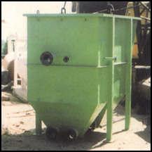 Lamella settlers are basically cross flow plate separators designed for removal of settleable solids.The water containing solids flows in a horizontal direction between the closely spaced plates in the plate pack. Completely laminar flow conditions are established while water flows across the plate pack from inlet to the outlet side.
Solids with the higher density than the carrier fluid will settle down into the sludge Compartment of the seprator, which is a sloped compartment to facilitate removal of the solid particles. The number and size of the plate is governed by the water flow rate and the settling velocity of the solid, which in turn are proportional to the diameter of the solids to be settled.
Lamella settlers are basically cross flow plate separators designed for removal of settleable solids.The water containing solids flows in a horizontal direction between the closely spaced plates in the plate pack. Completely laminar flow conditions are established while water flows across the plate pack from inlet to the outlet side.
Solids with the higher density than the carrier fluid will settle down into the sludge Compartment of the seprator, which is a sloped compartment to facilitate removal of the solid particles. The number and size of the plate is governed by the water flow rate and the settling velocity of the solid, which in turn are proportional to the diameter of the solids to be settled.
The distance between the plates is depending upon the concentration of the solids Sludge in the raw water. The plate distance can be varied, usually between 20 and 50mm, to allow for the different sizes of the settling particles, and to prevent clogging of the plate packs.The systems are fabricated in the mild steel and other materials are available on request.All K-Pack separators are custom built with respect to the number of plates in the pack,the length of the plate distance between the plate and the plate incline.
The incline of the plate is set between 45 and 60 degrees depending upon the general nature of the oil and/or the sludge.
(density ,velocity ,concentration). The systems are fabricated in the mild steel, and other materials are available on the request. The oil separators are standard with oil and skimpie and 45 degree shaped compartment. The solids separators are optionally with a shiftless conveyor in the Sludge compartment
Applications
• Mineral oil industry
• Edible oil industry
• Metal industry
• Ceramic industry
• Galvanic industry
• Mines
• Sand separation after washing of contaminated soil
• Food industry
Turnkey Project Solutions in ETP/WTP/ WWTP
 Global environmental awareness and environmental legislation requires companies to operate in an environmentally acceptable way. End product users insist upon finest environmental standards in deciding to purchase a product. So an economical solution is needed to install equipment and systems to achieve all these parameters.
K-Pack offers Turnkey Solution to all Industrial manufacturers to reduce cost of raw material and fresh water while reducing consumption of these valuable inputs.
We help optimize effluent discharge thus creating efficient and cost effective operation, by reducing waste and recycling water.
We provide treatment plants for industries which include:
• Food and beverage
• Dairies Industry
• Leather
• Petrochemical Plants
• Textile dyers & washer
• Rubber and many more
Wastewater Treatment when run efficiently in a manufacturing unit can give substantial cost savings in all areas including -
• Primary Treatment
• Biological
• Secondary
• Tertiary
• Sludge
Our Turnkey Solutions include Water Treatment Plants also in which we offer:
• Drinking / Potable water
• Water softening
• Lamella clarifier
• Clear flocculation
• Filters
• Reverse Osmosis
• Chlorination units
• Ozone treatment
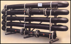
PFR Pipe Flocculator
 Coagulation And Flocculation by controlled Turbulence
The pipe flocculator is a plugflow reactor in which processes such as coagulation, flocculator, demulsification, precipitation and pH control can take place under hightly controlled and well defined conditions.
The above mentioned processes take place under turbulent flow conditions. At the chemical injection points the pipe diameter is adapted to ensure instantaneous mixing of chemicals and wastewater. Through the cross-section of a pipe the mixing intensity is virtually homogeneous. Reaction time is determined by the pipe length and flowrate and based on the exact requirements, no excess is required. In the plug flow reactor the process can be influenced at any time as opposed to tank reactors, where only one conditions per tank can be maintained.
Generally speaking a pipe flocculator is used where a coagulant, a flocculant and optionally a chemical for pH correction are dosed in sequence for the removal of turbidity and/or COD or precipitants.
The use of a pipe flocculator in combination with a flotation system can give COD removals to upto 95%.
K-Pack Systems has a wide experience in chemical treatment, particularly in the use and selection of coagulants and flocculants in combination with a PFR pipe flocculator. The PFR pipe flocculator is exceptionally suitable for our latest developments in the non-toxic bio-degradable coagulants and flocculants range.
Specific Details and characteristics :
• High quality and durable materials like HDPE. PVC, MS pipes
• No Shorcircuiting and hardly and backmixining
• No retention time distribution.
• Homogeneous mixing throughout the cross section
• Completely predictable and controlled mixing environment
• No moving Parts
• No additional energy source
• All required process conditions and chemical additions in a single unit.
• Uniform floc growth
• Small space requirements
• Exchange mixing pieces.
Available Models :
• Standards units are available upto a flow of 400 m3/hr.
• Customized units for special applications.
K-Pack Systems engineers can perform onsite tests to determine :
• Process parameters for coagulation
• Flocculation – separation
• Chemical and additive requirements
• Maximum achievable reductions in pollution load.
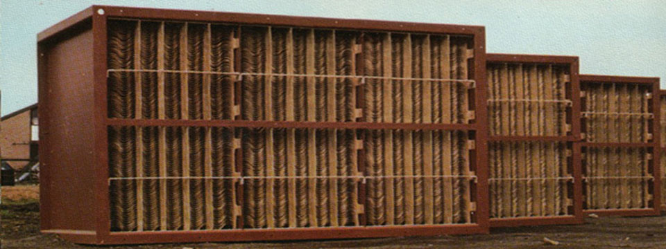
Corrugated Plate Packs
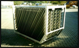
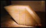
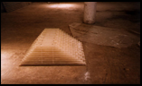 The corrugated plate pack represent the very heart of our various purification systems consisting of a number of parallel corrugated plates (see photograph). These are framed in a housing and the whole pack is stiffened by a frame made from plastic material and/or steel. The liquid to be treated flows through the spaces between the corrugated plates. Flow through the pack is laminar thus allowing the separation to take place under ideal conditions. In addition, much attention has been given to the profile of the corrugated plates. These have been chosen so that a smooth transfer and compaction of the separated particles is effected. To promote equal and uniform supply to the plates, specially designed flow baffles are used. In order to reduce the frictional resistance between the separated material and the corrugated plates to the minimum, particular attention was paid to the smoothness and hardness of the plate surface. The corrugated plates as well as the casing are made from glass fiber reinforced isophtalacid polyester resin. This material is resistant to the most frequently used chemical additives and temperatures. For applications under more aggressive conditions bisphenolic polyester resin or another suitable material is used. For erection and inspection purposes the plate pack has been fitted with lifting eyes so that it can be easily removed from or replaced into the installation. Upon request these plates can be made of other GRP resins like Orthopthalic acid, Bisphenol and Vinyl Ester Resins. Stainless steel packs have also been supplied as a special case.
